Equipment Compatibility
EES Amended Silicates prides itself on finding the right solutions to the challenges facing operators of coal fired boilers: innovative, cost-effective products, suitable equipment and expert advice.
A traditional feed system designed for PAC is often a design that will not optimally feed Amended Silicates (AS) nor recent generation PAC products. EES Amended Silicates (in conjunction with Jenike & Johanson, CH2M Hill now Worley Parsons and Nol-Tec Systems) developed two concepts for feeding AS that also accommodate Powdered Activated Carbon (PAC).
Gas Assisted Discharge
This approach is most appropriate for new system installations. Converting an existing silo to incorporate a gas assisted discharger (GAD) is expensive and the installation is cumbersome. By adopting a design that incorporates a GAD, utilities are able to optimally feed both AS and PAC (existing and next generation) with enhanced performance, thus avoiding future expenses to modify the feed system.
GAD Design
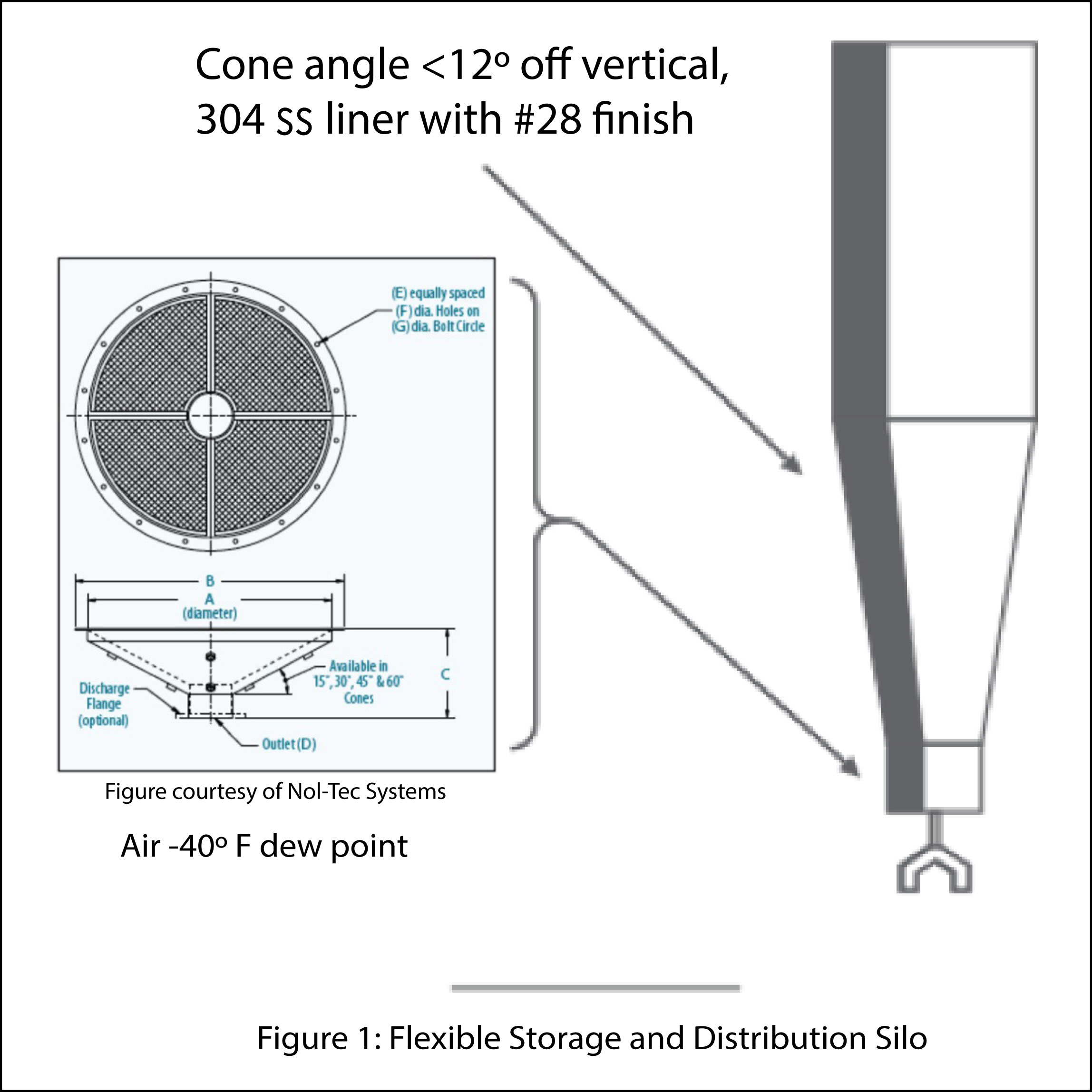 EES Amended Silicates worked extensively with Jenike & Johanson to determine the flow properties of Amended Silicates (AS) and to translate that information into a design that facilitates reliable material feed. Due to performance requirements of the feed system and a difference in properties between AS and PAC, it is impractical to design one system that is able to feed both materials in unassisted gravity flow. Based on GAD tests, it is possible to utilize one design to feed both materials using an GAD at the bottom of the silo. A concept schematic for the proposed feed system is provided in Figure 1. The GAD is located at the bottom of the silo cone. An air permeable membrane, inside the base of the GAD, allows dry pressurized gas to flow into the material in the bottom of the silo, locally fluidize it and cause it to flow easily and reliably to a centally located discharge pipe.
Nitrogen Injection
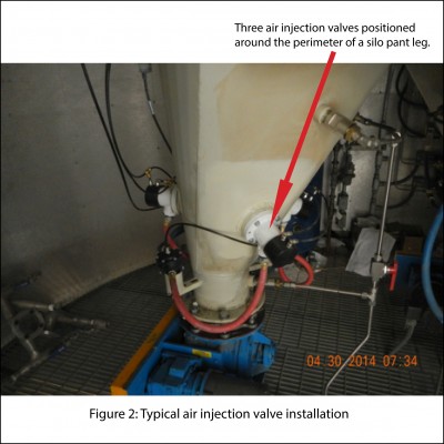
An alternate approach to the GAD concept is to utilize strategically located nitrogen injection valves that direct a short duration pulse of N2 into the media stored in the silo. The concept is to exploit the gas pulse to overcome cohesive forces in the material to minimize any tendency to arch, bridge or rathole. An added benefit of this approach is that the nitrogen inerting promotes reactivity of AS. EES Amended Silicates has retrofitted three silo systems to incorporate the features noted above - all systems are operating reliably and consistently. A typical installation is shown in Figure 2.
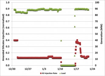
Feed stability has been demonstrated in the retrofitted silos during extended operation.
Figure 3 depicts AS injection rate and unit load for an approximate one month period. The AS injection rate is stable at a fixed rate and a controlled response is shown after a unit outage and subsequent feed rate adjustments.
The balance of the storage and feed system is similar to most bulk solids feed systems currently in use for PAC. Some key design features EES Amended Silicates recommends are:
- Solids metering performed with loss in weight feeders in combination with either a dry air driven eductor or a rotary valve that feeds material into the flowing transport air stream. The rotary valve is favored for higher flow rates and pressure-drops common to systems with long transport distances (>300 ft); the eductor system works well to deagglomerate particles and is best suited for low pressure drop/shorter-distance situations.
- Due to the abrasive nature of PAC and EES Amended Silicates materials, it is recommended that piping systems be configured such that sections wherein flow direction changes be augmented with ceramic lining to minimize wear.
- Manifolds utilized to split flow to ducts and/or lance arrays employ ‘spider’ manifolds that provide a gradual change in flow direction and that abrupt changes - such as with a ‘tee’ - are avoided.
- Since AS is a dense material, ~45 lb/ft3 (function of consolidating pressure), EES Amended Silicates recommends a minimum transport velocity that maintains dilute phase flow to avoid particle saltation.
The final elements in the reagent delivery system are the injection lances. EES Amended Silicates recommends that CFD modeling be used to investigate and optimize lance spacing to establish the best location(s) for reagent injection. Typically, lances are spaced no more than 30” apart. Further, multiple discharge points (spaced no more than 30” apart along a single lance) are provided by running parallel pipes to different depths, thus establishing a more uniform dispersion of material along the length of the lance.
Resources
Based on the design requirements set in collaboration with CH2M Hill and the work described above, a complete specification for a system to feed AS and PAC was developed. That system specification is available from EES Amended Silicates and utilizes the AAD approach.
EES Amended Silicates has provided technical support to multiple projects to convert systems originally designed to feed PAC, to feed Amended Silicates. Contact EES Amended Silicates for consultation on this and other requirements.
Further detailed information on Amended Silicates, Testing and Engineering Services is available to interested parties. Please contact Thomas Gale, Director of Technology Development